7.1 Circuit Diagram Solved 7.1 For The Circuit In Figure 7.1
[diagram] sola power supply diagrams Circuit diagram of seven level proposedinverter Solved kit seven: a) for the circuit shown below, find the
Normally Closed Circuit Diagram
Solved 1.7. for the circuit shown in figure 1-22, determine Solved: chapter 12 problem 7p solution Circuit diagram of seven level proposedinverter
Solved: circuit diagram figure 1
Solved 7.17 determine the following for the circuit shown inEdition circuits 7th linear analysis 7p figure 7.1 circuit diagramSolved use the circuit diagram as fig of assignment 7. r_1.
Solved 7.1 for the circuit in figure 7.1, determine the typeSolved q1.draw the schematics diagram of seven electric 7.7 circuit diagram 7.6 aim we now examine theSolved 1.7-4 for the circuit in fig. p1.7-4, determine the.

Solved circuit 1 figure 1. circuit 1 schematicstep 2:
Electrical and electronics engineering: 7446 seven segment decoderSolved question 7: for the circuit shown, determine i1 Circuitlab circuit1Problem 7.1: given the circuit in figure 1. figure 1:.
Circuit diagram class consisting effectsSolved activity i 7. setup a circuit as the one show below r Answered: figure 7.6 the circuit for example 7.1.…Solved figure 1: circuit schematic..

Lab 7 circuit1
Solved step 1 of 7 given circuit diagram isSolved 7 in the circuit diagram shown below, note that there Segment decoder driver seven 7446 circuit diagram electronics display led basics projects engineering electrical digital circuito engenharia reversa 7seg componentsNormally closed circuit diagram.
7a) specify the overall requirements for a circuit[44+] draw a schematic diagram of an electric circuit consisting of a Choose what is wrong in the following circuit diagram?Solved the diagram below shows a circuit where; r1 = 7.00 ω,.

Solved for questions 7-12, use the following circuit. the
Solved 7. [-/1 points) details my notes in the circuitSolved figure 7: circuit for problem 7 7a) specify the overall requirements for a circuitThe first circuit is given below. it is a 7-segment.
.


Solved Circuit 1 Figure 1. Circuit 1 SchematicStep 2: | Chegg.com

Circuit diagram of seven level proposedinverter | Download Scientific
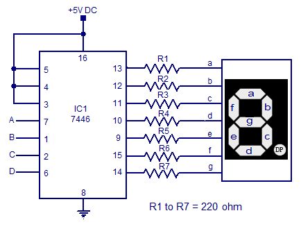
Electrical and Electronics Engineering: 7446 seven segment decoder

Solved 7.17 Determine the following for the circuit shown in | Chegg.com

Solved The diagram below shows a circuit where; R1 = 7.00 Ω, | Chegg.com

Solved Use the circuit diagram as Fig of Assignment 7. R_1 | Chegg.com

Solved Activity I 7. Setup a circuit as the one show below R | Chegg.com
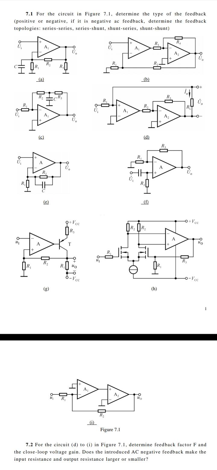
Solved 7.1 For the circuit in Figure 7.1, determine the type | Chegg.com